Compuprint 10300 User Manual
Browse online or download User Manual for Printers Compuprint 10300. Compuprint 10300 User Manual
- Page / 170
- Table of contents
- BOOKMARKS
Rated. / 5. Based on customer reviews
- Rev. 01 1
- 33 Kg / 73 Lbs 9
- Power Switc 15
- 31.5 in 16
- Then press 18
- Ribbon Winding Knob 19
- OFF LINE M1 33
- ON LINE M1 34
- ↑ arrow key 36
- PARK key to eject the paper 37
- PARK key to 37
- Fron t 38
- ON LINE Key 40
- PROGRAM Key 40
- MACRO Key 40
- PATH/PARK Key 43
- Key Combinations 43
- Main Structure 47
- PRINT OUT? NO 48
- PRINT OUT? YES 48
- Emulation Options 49
- IBM National Character Sets 53
- Parallel Interface 59
- Serial Interface 62
- Input Buffer Size 67
- LAN Interface Parameters 68
- PROGRAM key 71
- Functions 74
- TEAR ADJUST: xxx 82
- ↓ or PROG 83
- MACRO PARAMETER BLOCK 85
- CONFIGURATION MENU BLOCK 85
- User Macro Parameters 88
- Font Selection 94
- Pitch Selection 95
- Tear Delay Mode 100
- Selecting Another Macro 106
- STORE? QUIT 108
- STORE? SAVE 108
- STORE? CURRENT 108
- Clear Margin 117
- Barcode Guard Bar Enable 119
- LOAD FRONT 2 120
- LOAD FRONT 1 120
- PROGRAM key is disabled) 124
- ON LINE, MACRO 124
- PATH key) 125
- PATH key) or the PARK key is 125
- PARK key again to 125
- PATH key) or the PARK key 127
- EJECTING 128
- TEAR IF NECESS 128
- EJECT PAPER 128
- ALTERNATE key 129
- PARK key 129
- PATH key. The display shows: 131
- PARK key. The display shows: 131
- Solution 151
- Printing Characteristics 162
- Paper Handling 165
- Consumables 169
- Options 169
- Standards 169
Summary of Contents
Page 1 - Rev. 01
UUsseerr MMaannuuaall Rev. 01 78413012-001 Sett. 08
Page 2
6 RReemmoovvaall ooff tthhee SShhiippmmeenntt LLoocckkss 1. Open the tractor area cover and make sure that you remove the shipment lock from the
Page 3
96 Tear Delay Mode TEAR NORMAL ↑ TEAR DELAY 1 → or ← TEAR DELAY … → or ← TEAR DELAY 5 → or ← ↓ STRONG IMPACT This item defines the time that prin
Page 4
97 Print Impact Strength TEAR DELAY 1 ↑ STRONG IMPACT → or ← SOFT IMPACT → or ← ↓ PERFOR. SAFE NO STRONG IMPACT The impact strength of the print
Page 5
98 Quiet Printing PERFOR. SAFE NO ↑ QUIET PRINT OFF → or ← QUIET PRINT ON → or ← ↓ AUTOGAP 0 QUIET PRINT OFF The function is disabled. Printing a
Page 6
99 Adjusting the Distance of the Print Head QUIET PRINT OFF ↑ AUTOGAP -5 → or ← AUTOGAP ... → or ← AUTOGAP +3 → or ← MANUAL GAP → or ← FIXED GAP
Page 7
100 Horizontal Character Tuning AUTOGAP 0 ↑ TUNING: HORIZ 0 → or ← TUNING: HORIZ ... → or ← TUNING: HORIZ 60 → or ← ↓ TUNING: VERT 0 These valu
Page 8
101 Resetting the Macro Parameters to the Factory Defaults TUNING: VERT. 0 ↑ MACRO -> MFG NO → or ← MACRO -> MFG YES → or ← ↓ NEXT MACRO? NO
Page 9 - 33 Kg / 73 Lbs
102 Selecting Another Macro MACRO -> MFG NO ↑ NEXT MACRO? NO → or ← NEXT MACRO? YES ↓ ↓ CONFIG MENU NO MACRO#1 To pass over to another
Page 10
103 Passing over to the Power-On Configuration At this point of the setup, it is possible to pass over to the Power On Configuration functions setting
Page 11
104 Storing the values HEX DUMP NO ↑ STORE? QUIT → or ← STORE? SAVE → or ← STORE? CURRENT → or ← PROG EXIT STORE? QUIT This setting does not s
Page 12
105 AANNSSII EEmmuullaattiioonn The following items appear only when the ANSI emulation has been selected. ANSI Character Sets EMULATION ANSI ↑
Page 13
3. Open the upper printer cover and remove the fixing strip from the print head and from the bail (two strips). Keep all the packing material, toget
Page 14
106 ANSI Code Pages CH.TAB.. CODE437 ↑ NATION USA → or ← NATION … → or ← NATION CYRILLIC → or ← ↓ RIS ENABLE YES The following code pa
Page 15 - Power Switc
107 SI/SO Control RIS ENABLE YES ↑ SI/SO CTL YES → or ← SI/SO CTL NO → or ← ↓ AUTO CR YES If the printer receives a command (SI or SO) f
Page 16 - 31.5 in
108 Prime on Delete AUTO CR YES ↑ PRIME ON DEL YES → or ← PRIME ON DEL NO → or ← ↓ CONTRL IN DG YES If the printer receives a command (D
Page 17
109 Vertical Expansion CONTRL IN DG YES ↑ EXPAND UP YES → or ← EXPAND UP NO → or ← ↓ ALT GRAPHICS YES This setting defines the vertical
Page 18 - Then press
110 8-bit Control ALT GRAPHICS YES ↑ 8 BIT CTRL YES → or ← 8 BIT CTRL NO → or ← ↓ S/SUB SCRIPT YES If the printer receives a control co
Page 19 - Ribbon Winding Knob
111 ESC+Control Code S/SUB SCRIPT YES ↑ ESC+ CTR CODE YES → or ← ESC+ CTR CODE NO → or ← ↓ VT NOT SET YES In this setting the control co
Page 20
112 Double Line Feed VT NOT SET YES ↑ DOUBLE LF YES → or ← DOUBLE LF NO → or ← ↓ DOUBLE LF YES If the printer receives a command (LF) fr
Page 21
113 Clear Margin AUTO WRAP YES ↑ CLEAR MARGIN YES → or ← CLEAR MARGIN NO → or ← ↓ BACKOP NINE Clears (Y) or preserves (N) top and bottom
Page 22
114 Backup Option CLEAR MARGIN YES ↑ BACKUP NONE → or ← BACKUP BC → or ← BACKUP OS → or ← BACKUP BOTH → or ← ↓ GUARD BAR YES BC The p
Page 23
115 Barcode Guard Bar Enable BACKUP NONE ↑ GUARD BAR YES → or ← GUARD BAR NO → or ← ↓ EMUL. OPTIONS The printer will (Y) or will not (N)
Page 24
8 CCoonnnneeccttiinngg tthhee GGrroouunndd CCaabbllee For the printer model with the cabinet option, connect the ground cable in the interface are
Page 25
116 HHooww ttoo SSeelleecctt tthhee PPaappeerr PPaatthh The paper can be loaded into the printer using different paper paths. The messages indic
Page 26
117 HHooww ttoo UUssee tthhee TTeeaarr--OOffff FFuunnccttiioonn This function is used to match the paper perforation with the tear-off bar. For
Page 27
118 AAddjjuussttiinngg tthhee TTeeaarr--OOffff PPoossiittiioonn To check the Tear-Off Position proceed as follows: 1. Check if the paper perforat
Page 28
119 SSeelleeccttiioonn ooff tthhee TTeeaarr--OOffff MMooddee It is now possible to select the Tear-Off Mode. 1. Press the PROGRAM key when the p
Page 29
120 HHooww ttoo LLoocckk//UUnnlloocckk tthhee PPrriinntteerr SSeettuuppss To prevent not expertise persons changing the printer setup parameters
Page 30
121 HHooww ttoo HHaannddllee tthhee PPaappeerr PPaarrkkiinngg According to the setting of the TEAR item in the Program Setup, the paper parkin
Page 31
If TEAR NORMAL is selected: • When the paper is positioned at the first printable line and the paper path is changed (changing the Macro or pressing
Page 32
If TEAR AUTOMATIC is selected: • When the paper is positioned at the first printable line and the paper path is changed (changing the Macro or pressi
Page 33 - OFF LINE M1
If LABEL is selected: • When the paper is positioned at the first printable line and the paper path is changed (changing the Macro or pressing the P
Page 34 - ON LINE M1
125 If at power on the paper is already loaded in a paper path that is different to the paper path used by the macro which is valid at power-on, indep
Page 35
9 PPrriinntteerr PPaarrttss FFrroonntt VViieeww (*) The printer cabinet is available as an option.
Page 36 - ↑ arrow key
126 PPaappeerr HHaannddlliinngg PPaappeerr SSppeecciiffiiccaattiioonnss It is important to use the correct paper for obtaining the best performanc
Page 37 - PARK key to
127 FFaannffoolldd PPaappeerr LLooaaddiinngg LLooaaddiinngg PPaappeerr UUssiinngg tthhee FFrroonntt11 PPuusshh TTrraaccttoorr 1. To select t
Page 38 - Fron t
2. Open the Push tractors cover turning it upwards until it stops. 3. If installed, rotate the Front2 tractor outside of the printer. 128
Page 39
4. Unlock the sprockets of the Front1 tractor moving the sprocket levers up. Slide the left sprocket to the first printing column. For easier under
Page 40 - MACRO Key
55. Space the paper guides along the tractor bar. Open the left and right sprocket covers. . 6. If installed, insert the fanfold paper between th
Page 41
77. Hold the fanfold paper in front of the sprockets and insert the paper perforation on the left sprocket pins and close the sprocket cover. .8.
Page 42
9. Match the left sprocket for the first printing position, i.e. the left paper margin must match the ninth mark on the printer cabinet. 1234567891
Page 43 - Key Combinations
10. Adjust the right sprocket gently to remove slack from the paper. Make sure the paper is not taut. 11. Lock the left and right sprockets moving th
Page 44
12. If installed, reposition the Front2 tractor in its initial position. 13. If your printer is installed on a table, position the paper staple so th
Page 45
15. a) If only the Front1 push tractor is installed: - Press the LOAD/FF key to load the paper into the printer. b) If both the Front1 and the Front2
Page 46
10 RReeaarr VViieeww (*) The printer cabinet is available as an option.
Page 47 - Main Structure
- If the printer is not installed on the cabinet, make sure that there is enough space to stack the printed paper: 136
Page 48 - PRINT OUT? YES
137 LLooaaddiinngg PPaappeerr UUssiinngg tthhee FFrroonntt22 TTrraaccttoorr To load paper in this way, it is necessary to install the upper trac
Page 49 - Emulation Options
2. Open the tractor area cover turning is upwards until it stops. 138 3. Unlock the Front2 tractor sprockets moving the sprocket levers up.
Page 50
4. Space the paper guides along the tractor bar. Open the sprocket covers of the left and right sprocket. 5. Hold the fanfold paper in front of the
Page 51
7. Position the left sprocket for printing, matching the left paper margin with the eleventh notch on the printer cabinet and lock it in place. 1234
Page 52
9. Open the printer cabinet door and lay the paper onto the lower shelf inside the printer cabinet. 10. Close the printer cabinet door and the tracto
Page 53 - IBM National Character Sets
142 PPrriinntteerr MMaaiinntteennaannccee aanndd TTrroouubblleesshhoooottiinngg CClleeaanniinngg tthhee PPrriinntteerr Make sure the printer
Page 54
143 RReeppllaacciinngg tthhee RRiibbbboonn CCaarrttrriiddggee 1. Make sure that the printer is turned off for at least 15 minutes. Pay attentio
Page 55
4. Free the shifter holder pushing the tab towards the rear and pulling the shifter holder up. 5. Remove the used ribbon cartridge by lifting it u
Page 56
145 PPrriinnttiinngg tthhee SSeellff TTeesstt If you need to know any printer setting, and to check if the printer is working well, print the self
Page 57
11 LLeefftt SSiiddee VViieeww Power Switch IInnssiiddee VViieeww
Page 58
146 EErrrroorr HHaannddlliinngg When an error condition occurs: • the printer is disabled; • the first message on the display indicates the erro
Page 59 - Parallel Interface
147 Messages Indication Solution BUFFER OVERFLOW CHARACTER LOST A buffer overflow condition occurred (for the serial interface). Turn the printer off
Page 60
148 Messages Indication Solution PAPER JAM CHECK ALL PATHS A paper jam error condition occurs in the paper path. Check all the paper paths and remove
Page 61
149 RReeppaacckkiinngg tthhee PPrriinntteerr ffoorr SShhiippmmeenntt If you need to ship your printer, it is necessary to repack it to avoid dama
Page 62 - Serial Interface
2. Open the upper printer cover and fix the print head and the bail with the fixing strip. 3. Open the tractor area cover, move the paper guides to
Page 63
4. With the help of another person move the printer onto the transport foam on the transport pallet. Insert the plastic bag over the printer and the
Page 64
7. Close the packing box and fix it to the transport panel by means of the packing strip, inserting the plastic angles between the packing strip and
Page 65
153 OOppttiioonnss TThhee CCoonnttrroolllleerr BBooaarrdd The printer’s interface available configurations are: • Controller board with serial, p
Page 66
154 IInnssttaalllliinngg tthhee CCoonnttrroolllleerr BBooaarrdd Follow the reported instruction in case of Controller Board replacement. Handlin
Page 67 - Input Buffer Size
Perform the following steps to replace the Controller Board: 1. Ensure that the printer is powered off. Installing the Controller Board with the prin
Page 68 - LAN Interface Parameters
12 SSeettttiinngg UUpp YYoouurr PPrriinntteerr CChhoooossiinngg aa SSuuiittaabbllee LLooccaattiioonn Consider the following points when you ch
Page 69
156 5. Gently push the Controller Board into the printer until it is seated in the connector inside the printer. The Controller Board is correctly s
Page 70
6. Attach the Controller Board with the two screws using the screwdriver that came in the Controller Board box. 157
Page 71 - PROGRAM key
158 PPrriinntteerr SSppeecciiffiiccaattiioonnss Printing Characteristics Print Head Matrix 24 pins Print Head Life 800 mil characters (draft)
Page 72
159 Print Matrix (horizontal x vertical) Draft Quality HS Draft Normal Best Draft NLQ LQ 10 cpi 9 x 12 12 x 12 12 x 24 36 x 12 36 x 2
Page 73
160 Print Styles Draft - Courier - OCR B - Gothic - Prestige - Present - OCR A - Script Print Attributes Sub-superscript, Underline, Overscore, Ital
Page 74 - Functions
161 Bar Codes UPC-A, UPC-E, EAN-8, EAN-13, UPC-EAN 2, UPC-EAN 5, Code GP, MSI Plessey, Code BCD, C2/5-3 BAR, Code 39, Code 128, Code 11, Code 93, Cod
Page 75
162 Standard Functions • Automatic print head gap adjustment (AGA) • Automatic paper path switching via operator panel or S/W commands • Paper par
Page 76
163 Reliability MTBF Mean Time between failure: 10000 hours at 25% DC MTTR Mean Time To Repair: 30 minutes Workload 60000 pages/month (ECMA 132 - 4
Page 77
164 Paper Conditions Temperature 16° to 24° C Relative Humidity 40% to 60% RH (non condensing) Physical dimensions Height 350 mm (13,77 inch
Page 78
165 Consumables Black “Long Life” cartridge (25 million characters) PRKN102-1 Options Printer Cabinet PRFN-PD2 Front2 Tractor PRFN2TR6 Controll
Page 79
13 RRiibbbboonn CCaarrttrriiddggee IInnssttaallllaattiioonn Make sure that you are using only Compuprint original consumables. 1. Make sure that t
Page 80
166 78413012-001 Sferal WWT proprietary. All trademarks herein recalled are registered by their respective companies.
Page 81
3. Turn the printer on and wait for printer initialization. Then press the ON LINE key to put the printer in OFF-LINE mode (check ON LINE indicator
Page 82 - TEAR ADJUST: xxx
5. Before installing the ribbon cartridge turn the ribbon-winding knob in the arrow direction (located on the cartridge) to take up slack in the ribbo
Page 83 - ↓ or PROG
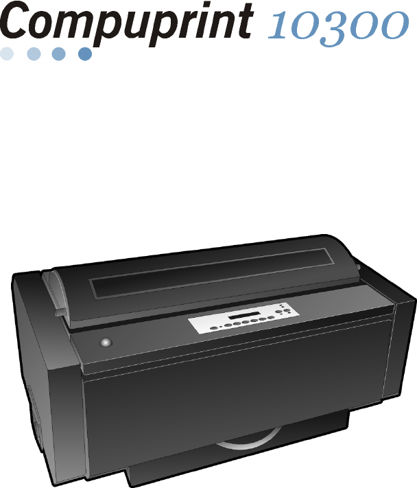
Compuprint Products Information Compuprint Products InformationThanks for choosing the 10300 printer. Your printer is a reliable working equipment
Page 84
7. Slide and insert the ribbon guide between the print head and the ribbon guide mask holding it perpendicular to the print head. Make sure that the
Page 85 - CONFIGURATION MENU BLOCK
9. Turn again the ribbon-winding knob in the arrow direction (located on the cartridge) to take up slack in the ribbon. 10. Push the cartridge down g
Page 86
18 FFrroonntt22 PPuusshh TTrraaccttoorr IInnssttaallllaattiioonn An additional front push tractor may be installed on the printer. This Front2 pus
Page 87
3. Push the Front 2 tractor until it is fully engaged. 4. Insert the connector cable in the electrical connector located in the lower push tracto
Page 88 - User Macro Parameters
5. Rotate the Front2 push tractor onto the Front 1 push tractor. 20
Page 89
21 RReemmoovviinngg tthhee FFrroonntt22 PPuusshh TTrraaccttoorr If you need to remove the upper push tractor, turn the printer off. Disconnect th
Page 90
22 HHoosstt CCoommppuutteerr CCoonnnneeccttiioonn This printer can be connected to your host computer via different available interfaces on two alt
Page 91
The interface connectors are located on the rear of the printer. SERIAL INTERFACE23 USB INTERFACEPARALLEL INTERFACE LAN INTERFACEPARALLEL INTERFACE
Page 92
24 SSooffttwwaarree DDrriivveerr SSeelleeccttiioonn At this point it is necessary to configure your printer for your application package. The insta
Page 93
25 PPoowweerr CCoonnnneeccttiioonn The power outlet must be compatible with the plug of the printer’s power cable. Always use a grounded outlet. 1.
Page 94 - Font Selection
FFFFCC NNootteess This equipment has been tested and found to comply with the limits for a Class A digital device, pursuant to Part 15 of the FCC Ru
Page 95 - Pitch Selection
4. If you need to turn the printer on, press the power switch in the I position (ON). 26
Page 96
27 SSeelleeccttiinngg tthhee DDiissppllaayy LLaanngguuaaggee The display messages for this printer can be displayed in five different languages: E
Page 97
28 CCoonnffiigguurriinngg tthhee PPrriinntteerr OOppeerraattoorr PPaanneell PPrreesseennttaattiioonn The operator panel enables you to perform
Page 98
29 DDiissppllaayy MMeessssaaggeess The printer display is used to indicate the printer status or to request an user intervention. When the printer i
Page 99
• when there is no paper loaded and the printer is off line (ON LINE indicator unlit): • when there is no paper loaded and the printer is on line (
Page 100 - Tear Delay Mode
31 The following messages appear to indicate other printer conditions or user intervention requests. The list is in alphabetical order. Message Descri
Page 101
32 Message Description MICRO FEED UP The paper is fed in microsteps forwards when pressing the ↑ arrow key. OPER. INTERRUPTED This message is display
Page 102
33 Message Description TEAR OFF PAPER EJECT PAPER These messages are displayed when the printer receives a paper ejecting command (TEAR NO item has b
Page 103
34 IInnddiiccaattoorrss Lit when the printer can receive and print data (printer online). Blinks when there is data in the buffer and the printer i
Page 104
35 FFuunnccttiioonn KKeeyyss Pressing the function keys it is possible to activate the functions indicated by the word or symbol signed near the key
Page 105
TTaabbllee ooff CCoonntteennttssCompuprint Products Information ... iiFFC Notes ...
Page 106 - Selecting Another Macro
36 ON LINE Key ON LINE Normal Function Enables or disables the printer. • If this key is pressed while powering the printer on, the self test is pr
Page 107
37 FONT Key FONT Normal Function Selects the font to be used with the currently selected pitch. The selected font is valid until the printer is turned
Page 108 - STORE? CURRENT
38 ALTERNATE Key ALTERNATE Normal Function Enables the alternative key functions. If the printer is receiving print data, press the ON LINE key befor
Page 109
39 PATH/PARK Key PATH Normal Function Selects one of the paper paths in offline status. The parameters of the displayed path are set after 2 seconds w
Page 110
40 PPrriinntteerr SSeettuuppss The main printer setup parameters can be selected via the operator panel. The setup parameters are divided into two p
Page 111
41 LLeeaavviinngg tthhee PPrriinntteerr SSeettuuppss • Pressing the PROGRAM key in the Power-On Configuration the printer exits from the setup an
Page 112
42 PPoowweerr--OOnn CCoonnffiigguurraattiioonn The default values of the various functions are indicated in bold. EEnntteerriinngg tthhee PPoowwee
Page 113
Main Structure This figure shows the structure of the Power-On Configuration and how to move inside the Setup. 43
Page 114
44 The setup item Functions groups the following printer functions: • Buzzer setting, • Paper loading sequence, • Bar code density, • Text printi
Page 115
Emulation Options This setup defines the available options according to the selected emulation and is structured as follows: Options 45
Page 116
1 GGeettttiinngg ttoo KKnnooww YYoouurr PPrriinntteerr PPrriinntteerr FFeeaattuurreess • 24 Needle Print Head • 136 columns @10 cpi • High
Page 117 - Clear Margin
46 Setting the Emulation Options Printer Emulation PRINT OUT? NO EMUL. OPTIONS ↑ ↑ EMUL. OPTIONS → EMUL. EPSON LQ → or ← ↓ EMUL. IBM XL24
Page 118
47 EPSON Character Sets EMUL. EPSON LQ ↑ CHAR. SET CS1 → or ← CHAR. SET CS2 → or ← CHAR. SET ITALIC → or ← ↓ NATION CP437 These items se
Page 119 - Barcode Guard Bar Enable
48 EPSON National Character sets CHAR. SET CS2 ↑ NATION CP437 → or ← NATION … → or ← NATION LATIN A1 → or ← ↓ AUTO CR YES The following
Page 120 - LOAD FRONT 1
49 IBM National Character Sets CHAR. SET CS2 ↑ NATION CP437 → or ← NATION … → or ← NATION FARSI2 → or ← ↓ AUTO CR NO The following natio
Page 121
50 CR Code Behavior NATION xxx ↑ AUTO CR NO → or ← AUTO CR YES → or ← ↓ AUTO LF NO AUTO CR NO No automatic carriage return is performed
Page 122
51 LF Code Behavior AUTO CR xx ↑ AUTO LF NO → or ← AUTO LF YES → or ← AUTO LF HOST → or ← ↓ 20 CPI IBM NO or BAR CODE NATIV AUTO
Page 123
52 IBM Compressed Printing These items are displayed only if the IBM emulation is selected. AUTO LF NO ↑ 20 CPI IBM NO → or ← 20 CPI IBM YES →
Page 124 - ON LINE, MACRO
53 Bar code mode 20 CPI IBM NO or AUTOLF NO ↑ BAR CODE NATIV → or ← BAR CODE ALTER → or ← ↓ EMUL. OPTIONS BAR CODE NATIV Enables bar c
Page 125 - PARK key again to
Interface Settings Depending upon the installed Controller Board, the printer can be equipped with different interfaces to connect to the host system.
Page 126
Parallel Interface This setup defines the use of the parallel interface and is structured according to the interface specific parameters. Parallel Int
Page 127 - PATH key) or the PARK key
2 UUnnppaacckkiinngg YYoouurr PPrriinntteerr The following items are included in the box: Notify any damage to your supplier.
Page 128 - EJECT PAPER
56 Setting the Parallel Interface Parameters Interface Type INTERFACE PARALL INTERFACE ↑ ↑ PARALL INTERFACE → 1284 BIDIR. I/F → or ← ↓ C
Page 129 - PARK key
57 Number of Data Bits SELECT-IN HOST ↑ DATA BITS 8 → or ← DATA BITS 7 → or ← ↓ INP. BUFFER 2K Selection of the number of data bits: 7 or 8. Inp
Page 130
Serial Interface The following Serial Interface Parameters will display only if the Serial Interface is present. This setup defines the use of the ser
Page 131 - PARK key. The display shows:
59 Setting the Serial Interface Parameters Interface Type PARALL INTERFACE SERIAL INTERFACE ↑ ↑ SERIAL INTERFACE → SERIAL I/F 232 → or ← ↓
Page 132
60 Baud Rate SERIAL I/F 232 ↑ BAUD 300 → or ← BAUD 600 → or ← BAUD 1200 → or ← BAUD 2400 → or ← BAUD 4800 → or ← BAUD 9600 → or ← BAUD 1920
Page 133
61 Parity Check DATA BITS 8 ↑ PARITY NONE → or ← PARITY ODD → or ← PARITY EVEN → or ← PARITY MARK → or ← PARITY SPACE → or ← ↓ HANDSHAKE
Page 134
62 Handshake Protocol PARITY NONE ↑ HANDSHAKE DTR → or ← HANDSHAKE XONXOF → or ← ↓ CONNECTION LOCAL HANDSHAKE DTR The Handshake is perf
Page 135
63 Input Buffer Size CONNECTION LOCAL ↑ INP. BUFFER256 → or ← INP. BUFFER 2K → or ← INP. BUFFER12K → or ← INP. BUFFER32K → or ← INP. BUFFER64K → o
Page 136
LAN Interface The following LAN interface parameters will display only if the Ethernet 10/100 Mbit interface is present. This setup defines the use
Page 137
65 IP Assignment PARALL INTERFACE LAN INTERFACE ↑ ↑ LAN INTERFACE → IP ASSIGN FIXED → or ← ↓ IP ASSIGN DHCP → or ← FUNCTIONS ↓
Page 138
To unpack the printer proceed as follows: Keep the packing material in a safe place. It must be used if you need to repack the printer for shipment. 1
Page 139
66 Init Net Mask INIT IP ADDRESS 127.000.000.000 ↑ INIT NET MASK 000.000.000.000 → or ← INIT NET MASK … → or ← INIT NET MASK 255.255.255.255 →
Page 140
67 Init Host Name DEF. GATEWAY ID 000.000.000.000 ↑ INIT HOST NAME …………… → or ← PROGRAM key ↓ INIT WORKGROUP CMP_GROUP The host is identif
Page 141
68 Enable/Disable the SMTP Service INIT WORKGROUP workgroup ↑ SMTP ENABL. NO → or ← SMTP ENABL. YES ↓ ↓ LAN INTERFACE MAIL SERV.ADDRES
Page 142
69 E-mail Address This item is displayed only if the SMTP ENABL. function is selected YES. MAIL SERV.ADDRES 000.000.000.000 ↑ EMAIL ADDRESS xx
Page 143
Functions This item groups various printer functions, with which you can configure the printer. Functions Group Parameters 70
Page 144
71 Setting the Functions Group Items Enable/Disable the Buzzer SERIAL INTERFACE (*) or LAN INTERFACE (**) FUNCTIONS ↑ ↑ FUNCTION
Page 145
72 Paper Loading Sequence BUZZER YES ↑ SEQUENCE NONE → or ← SEQ. F1+F2 PUSH → or ← ↓ BAR CODE 120 DPI TThheessee iitteemmss aarree ddii
Page 146
73 Text Print Direction BAR CODE 120DPI ↑ TEXT DIRECT BI → or ← TEXT DIRECT UNI → or ← ↓ GRAPH DIRECT BI Selects the print direction for
Page 147
74 Bar Codes Print Direction GRAPH DIRECT BI ↑ BARCODES DIR. BI → or ← BARCODES DIR. UNI → or ← ↓ GRAPH H.S. YES Selects the print directio
Page 148
75 Paper Path at Power-On GRAPH H.S. YES ↑ P. ON PATH MACRO → or ← P. ON PATH LAST → or ← ↓ MENU ENGLISH P. ON PATH MACRO The paper path a
Page 149
4. Remove the accessories out of the packing box and slide the packing box off the printer. 4
Page 150
76 Selection of the Language of the Display Messages P. ON PATH MACRO ↑ MENU ENGLISH → or ← MENU ITALIANO → or ← MENU FRANCAIS → or ← MENU ES
Page 151 - Solution
77 Enable/Disable Lower Tractor Jam Sensor MENU ENGLISH ↑ F1 JAM SENS. Y → or ← F1 JAM SENS. N → or ← ↓ F2 JAM SENS. Y or TEAR ADJUST:xxx F1
Page 152
78 Adjusting the Tear-Off Position F2 JAM SENS. Y or F1 JAM SENS. Y or MENU ENGLISH ↑ TEAR ADJUST: +30 → or ← TEAR ADJUST: ... → or ← TEAR ADJUST
Page 153
79 Resetting to Factory Default Values With the BACK TO MFG function it is possible to reset all items in the Power On Configuration Setup and in the
Page 154
80 PPrrooggrraamm SSeettuupp The default values of the various functions are indicated in bold. EEnntteerriinngg tthhee PPrrooggrraamm SSeettuupp
Page 155
Main Structure Print out? YesMacro # 1Line sp. 6 lpi...Next Macro? NoConfig. Menu YesHex Dump YesLine sp. ...Next Macro? YesMacro # 4Print out? NoU
Page 156
82 Printout of the Printer Settings PRINT OUT? NO → or ← PRINT OUT? YES ↓ USER MACRO PRINT OUT? NO The setup is not printed. PRINT OUT? YES Th
Page 157
83 User Macro The USER MACRO item allows to prepare four printing environments (MACRO#1, MACRO#2, MACRO#3 and MACRO#4). Each macro is composed of a gr
Page 158
User Macro Parameters Macro #1 Macro #2Li ne sp. 6 lpiLine Sp. Lock NoLength 66 Li nesTop of Form 0Sk ipo ver 0Draft Mode NormQuality LQFont
Page 159
85
Page 160
5. With the help of another person, remove the two foam shells on either side of the printer, the plastic bag covering the printer and the two carton
Page 161
86 Line Spacing MACRO#1 ↑ MACRO#1 → LINE SP. 6 LPI → or ← LINE SP. 8 LPI → or ← LINE SP. 12 LPI → or ← LINE SP. 3L/30MM → or ←
Page 162 - Printing Characteristics
87 Page Length LINE SP. LOCK NO ↑ LENGTH 1 LINE → or ← LENGTH ... LINES → or ← LENGTH 244 LINES → or ← ↓ TOP OF FORM 0 These items set the
Page 163
88 Form Feed (FF) Command TOP OF FORM 0 ↑ IGNORE F.F. NO → or ← IGNORE F.F. YES → or ← ↓ SKIPOVER 0 IGNORE F.F. NO The Form Feed (FF) comman
Page 164
89 Draft Print Mode Selection SKIPOVER 0 ↑ DRAFT MODE NORM → or ← DRAFT MODE BEST → or ← DRAFT MODE HS → or ← ↓ QUALITY LQ DRAFT MODE NORM The
Page 165 - Paper Handling
90 Font Selection QUALITY LQ ↑ FONT Draft → or ← FONT Courier → or ← FONT OCR-B → or ← FONT Gothic → or ← FONT Prestige → or ← FONT Present → or ←
Page 166
91 Pitch Selection FONT Draft ↑ PITCH 5 CPI → or ← PITCH 6 CPI → or ← PITCH 7.5 CPI → or ← PITCH 8.5 CPI → or ← PITCH 10 CPI → or ← PITCH 12 CPI → o
Page 167
92 Micro Dot Print Mode PITCH 10 CPI ↑ 15&24CPI NORMAL → or ← 15&24CPI MICRO → or ← ↓ PITCH LOCK NO 15&24CPI MICRO The print mat
Page 168
93 Left Margin PITCH LOCK NO ↑ LEFT MARGIN 0 → or ← LEFT MARGIN ... → or ← LEFT MARGIN xxx → or ← ↓ RIGHT MARGIN 136 The Left Margin is set in
Page 169 - Standards
94 Zero Character Printing RIGHT MARGIN 136 ↑ SLASH ZERO NO → or ← SLASH ZERO YES → or ← ↓ PATH FRONT 1 You can select the Zero character print
Page 170
95 Tear-Off Mode PATH FRONT 1 ↑ TEAR NORMAL → or ← TEAR AUTOMATIC → or ← LABEL → or ← TEAR NO → or ← ↓ TEAR DELAY 1 TEAR NORMAL The Tear-Off Func
Related products and manuals for Printers Compuprint 10300
Printers Compuprint 4247-L03 User Manual
 (142 pages)
(142 pages)
 (48 pages)
 (44 pages)
Printers Compuprint 4247-Z03 User Manual
(204 pages)
(204 pages)
Printers Compuprint 4247-X03 User Manual
(200 pages)
(200 pages)
Printers Compuprint 9058 User Manual
(145 pages)
(145 pages)
Printers Compuprint 9058 User Manual
 (147 pages)
(147 pages)
Printers Compuprint 9058 User Manual
 (84 pages)
(84 pages)
© 2020, manymanuals.com. All rights reserved. | 0.028 s |
 Manymanuals.com
 Manymanuals.de
 Manymanuals.fr
 Manymanuals.it
 Manymanuals.pl
 Manymanuals.cz
 Manymanuals.es
 Manymanuals-pt.com
Comments to this Manuals